Another installment on common IPSC problems and their solutions! Here are two related problems that can use a common solution. First off, let’s talk about the specific problems, then we’ll tackle a solution.
NAT That Won’t Hairpin
This is an unfortunate reality. What I’m talking about are NAT devices/software that will not allow two nodes on the private network to communicate with each other through the public WAN IP address. It’s commonly called “hairpin” or “hairpinning” and “NAT loopback”. I’ve heard it called “full-cone NAT” in a number amateur circles, but that’s actually something completely different. It seems like a strikingly simple function, but there are an alarming number of NATs that won’t do it. There are tons of articles on the Internet about this, so I won’t explain it again — others have already done a great job. Some folks are dealing with a home router and can just go buy a new one, but sometimes that’s not the case — like if you talk your boss into letting you run your ham DMR repeater on the network at work… They’re probably not going to throw away a $20,000 firewall just because your ham repeater can’t play nicely with it. Here are some good resources to read more about NAT, NAT hairpin, etc.:
How to Hairpin on MikroTik RouterOS (with a description of the problem)
How to Hairpin on Ubiquiti EdgeMax routers (with a description of the problem)
Hairpinning on the Juniper SRX/J series routers
A boatload from Cisco with regard to multiple configurations an their ASA security appliance
Random Port Translations
Here’s another unfortunate scenario. IPSC link establishment works by the master repeater gathering a list of IP addresses and UDP port numbers of the peers that connect to it and distributing that list to every peer so that they can all communicate directly with each other. For example, if a peer repeater contacts the master, let’s say on IP:port 123.117.116.5:50000, then the master will tell every other repeater in the IPSC to contact it on 123.117.116.5:50000. It will also tell the new repeater the IP:port combinations of every other repeater in the IPSC system. Each peer, in turn tries to contact the others on the IP:port combination in the list received from the master. Those actions “open” state table entries in any firewalls that repeaters sit behind and allow bi-directional communication.
This system only works if the port (50000 in the example above) is either NOT translated, or translated to the same “outside” port for every session the repeater tries to establish. If each time the repeater tries to connect to another peer the source port gets translated to something different then it’ll never be able to establish a connection to the other peers — they’re all expecting the new repeater on the port the master repeater told them about. To be clear, what I’m talking about is the source port (50000 in this example) being translated to a different public port for each different repeater it attempts to communicate with.
By now you may be asking why on earth this would happen? Since the world has run out of IP address, a lot of ISPs are no longer handing out public IP addresses. This is especially prominent with wireless carriers who not only got into the Internet game late, but also have a huge explosion of devices to connect. Because they are connecting dozens (hundreds?) of customers with a single public IP address, the chances of a contention for a particular port number is considerably higher than when you have one public IP for your home. Many CGNAT (Carrier Grade NAT) systems will randomize ports just to ensure everyone is treated equally (poorly). Another reason is security. Some enterprises with very strict security postures believe that randomly changing source ports adds extra security as it helps obfuscate the program or service that initiated communication. But whatever the reason, random port manipulation is real, and it’s not likely to go away.
The Common Thread
In both cases, there is a common thread. Something is disrupting communication at the border of a LAN. The hairpin NAT problem usually manifests when multiple repeaters have to share the the same NAT. The repeaters on same NAT can communicate with the repeaters and/or bridge that is/are NOT on the same NAT, but cannot communicate with the repeaters that are. In the case of random port translation, the repeater in question can communicate with it’s master, but other peer relationships never get established. Both have to do with NAT problems, and there’s a way (ok, probably several) around it.
The Solution
First off, this solution has a fair amount of overhead and introduces more complexity, so it should only be used if there isn’t a way to address the root NAT problem — which would always be a better approach.
The common thread was that we have multiple devices in an IPSC system
that are separated with each other by a NAT that for whatever reason,
isn’t playing nicely. The solution is to use IPSC bridging to ensure
that where the IPSC traffic crosses the NAT, there are exactly two peers
in the IPSC: A single peer, and a single master. Probably the most
obvious method is where we have a bridge in the mix that can just
segment all of our repeaters off into multiple IPSC systems where each
contains one repeater and the bridge, thereby ensuring there are always
only two IPSC devices per IPSC system… Problem solved! Maybe.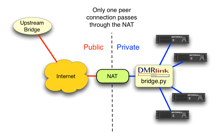
I recently ran into a situation where the bridge being used was a Rayfield/Ravennet c-Bridge, and the owner/operator of the bridge did not have the resources/desire to create the subdivision for several repeaters behind the same NAT that would otherwise be in the same IPSC system. A novel solution was implemented: Use another bridge. In this case we used the free, open source DMRlink and it’s bridge.py bridging application. I implemented DMRlink on the LAN (behind the NAT) with all of the repeaters. Next, I connected one instantiation of IPSC on DMRlink to with all of the repeaters. Finally, I created another IPSC with DMRlink that talked to the “upstream” c-Bridge. Now the new connection between DMRlink and the c-Bridge (the one that crossed the NAT) is a 2-device IPSC, and did not have any of the nasty NAT problems anymore. What’s better is, the c-Bridge owner/operator was thrilled because we reduced the number of IPSC peers (which is how the c-Bridge software is licensed – read: $$$) by three, since instead of four repeaters (IPSC peers), it now only say one (DMRlink).
Posted in Digital Radio Networking & TCP/IP Software VHF/UHF by .
A while back I posted an article about IPSC NAT problems and promised some follow-ups. This is the first one, and what I would consider a “brute force” attack on the problem: Move it all into a VPN. Before I dig in too deep, I want to give credit to Rick Wilson, WD5ETD of Tulsa, OK. Rick and I developed this solution together. Rick had a much larger IPSC network to deploy, and was really the one who proved the concept would scale.
I should start off with the design criteria. The merit of the solution might be lost without understanding the goals:
- Security: Completely isolate the repeaters from the public Internet.
- Obfuscate: IPSC looks like UDP VoIP traffic (it is) and some providers don’t like that.
- KISS: A simple “black box” approach for repeater owners.
- Cost Effective: We’re hams, no deep pockets, ’nuff said.
- Performance: It had to work really well, and be reliable.
These criteria could be met any number of ways, so at some point, I
just had to pick something and move forward. I know a lot of folks like
the prosumer routers running alternate firmware like DD-WRT, OpenWRT and a host of others, but I’ve become quite enamored with the MikroTik RouterBoard
products in the last few years. New devices cost less than used Linksys
home routers, and the OS is a real, professional grade product… though
the learning curve is a little higher, I’ve found this to be a very
compelling solution that supplies both hardware and software in one
shot, for one price, with commercial support. I settled on the MikroTik RouterBoard RB750GL (recently discontinued and replaced by the hEX) because I had a spare one, and the MikroTik RouterBoard hAP lite. The hAP lite is technically intended to be a combo switch/wireless AP, but at $23 $21 (no kidding), just shutting off the wireless interface and using it as a VPN endpoint was a real bargain!
I wanted to use a commercial cloud-based solution for the VPN server, mostly for the great network performance (a server at the end of residential connections, even really “fast” ones is a bad, bad idea). I know there’s been a lot of traction with Digital Ocean in the amateur community (and I have several VPSes with them myself) so I decided to use a different company: Atlantic.net. At this point I had a Linux VPN server (extra-small, $5/mo) and VPN clients in the form of MikroTik RouterBoards. How should I use them together? The quick and obvious choice was to use an IPsec-based VPN, but those are still notoriously difficult to set up and troubleshoot in many environments. I chose OpenVPN (definitely the underdog… are you noticing a theme here?), and used it in TCP mode in an attempt to hide the fact that I’m running VoIP traffic as some providers now marking down UDP and/or VoIP specifically (yes, I realize there’s a reason VoIP traffic uses UDP — this is part of why I wanted a high-performace connection for the server). This solution was easy since MikroTik has OpenVPN client and server already baked into the RouterOS.
The last piece of the puzzle is DMRlink from the K0USY Group (full disclosure: I’m the primary author of DMRlink). DMRlink will operate as a sort of application-level gateway, where one IPSC system is connected to repeaters via the VPN, and another is connected to upstream resources (public bridges such as DMR-MARC, DCI, etc.). To do this we used the bridge.py application from the DMRlink package, specifying the interface different IPSC instances would listen on.
I believe this is where Rick’s solution and mine diverged, as we both looked at L2 “switched” VPN and L3 “routed” VPN connections. I chose L3, and Rick used L2. In either scenario, the results are very similar. In my L3 solution, each MikroTik has a unique /24 network assigned from 10.100.0.0/16. These are statically chosen to use for the repeater-side networks on each MikroTik — the repeaters can be statically assigned an address, or the MikroTik can serve as a DHCP server to assign them. The OpenVPN server is told which /24 is associated with each “user name” so that when a MikroTik connects authenticates, that /24 is routed towards it. The OpenVPN server communicates through the VPN tunnels with each MikroTik over 172.16.100.0/24 a network used by the server to dynamically build tunnels to the clients (MikroTiks). Finally, DMRlink has one IPSC instance configured on the virtual tunnel (tun0) interface, and one configured on the public interface (eth0). All of the networks I’ve listed specifically, (10.10.0.0/8, 172.16.100.0/24, etc. were choices I made, anything in RFC1918 space could be used). This part is really important: The OpenVPN server does not route/forward traffic to the public internet from the VPN at all. There is no forwarding between tun0 and eth0 (see diagram below). DMRlink is listening on both interfaces, and bridges IPSC traffic between them — hence the application-level gateway description.
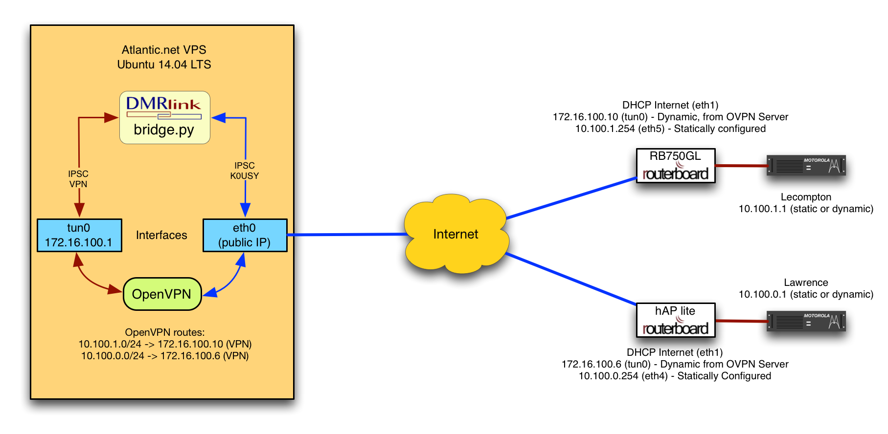
If multiple repeater IPSC systems are needed, bridge.py can simply be configured for multiple IPSCs on the tun0 interface using a different UDP port number for each. That’s it. the complete solution! Let’s recap the goals and how they were met:
- Security: The repeaters use DMRlink as an application-layer gateway, and have no direct IP connection to the internet.
- Obfuscate: IPSC traffic is now encapsulated in OpenVPN TCP packets to/from the repeaters.
- KISS: A small MikroTik RouterBoard for each repeater is all at the end-site.
- Cost Effective: $23 RouterBoard hAP lite and a $5/mo. VPS (which can server dozens of repeaters).
- Performance: Cloud hosted VPS and commercial-grade hardware endpoints.
This solution has been working and in place on the K0USY Group network for many months now. The MikroTiks, OpenVPN and the Atlantic.net VPS have been perfect. DMRlink, has had to be restarted a couple of times in several months, but generally has been stable as well. It’s important to note that this solution could probably be implemented with software version of the c-Bridge/TL-NET/Ravennet bridging software, which is preferred by most hams. The software appears to listen to all network interfaces, so while not quite as slick as DMRlink’s ability to specify the interface on a per-IPSC basis, there doesn’t appear to be any reason why the bridge role couldn’t be performed that way instead.
Posted in Digital Radio Networking & TCP/IP Software VHF/UHF by .
Aug 2015
24
A $25 Router with the Power of a $500 Router
Many inexpensive Linsksys WRT54G routers can be found on Ebay for less than $30. I have found the stock Linksys firmware requires a reboot every month or two and even has strange lockups. Not only that, the stock firmware has limited port forwarding and external antenna options. DD-WRT is user-friendly and an open source firmware project that offers a solution to your stock firmware woes. Better yet, DD-WRT supports more than 25 modem manufacturers. The best part is that it is very stable. I have found that I only need to reboot my router maybe once or twice a year.
DD-WRT also allows you to change your router into a wireless bridge,
meaning it can be modified by software to act more or less like a Wi-Fi
repeater and communicate with your main router in the house and extend
the range of your Wi-Fi. This is great for a “garage repeater.”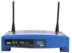 If your garage is too far from the house, no worries. You can
edit the configuration software to use only one external high gain yagi
or panel antenna connected to the router. External 2.4 GHz wireless
antennas can be found easily and at low costs these days. You can also
edit the power levels to mitigate interference between access points.
DD-WRT also supports VPNs.
If your garage is too far from the house, no worries. You can
edit the configuration software to use only one external high gain yagi
or panel antenna connected to the router. External 2.4 GHz wireless
antennas can be found easily and at low costs these days. You can also
edit the power levels to mitigate interference between access points.
DD-WRT also supports VPNs.
So, the next time you fight with a counter-intuitive graphical user interface, one with annoying limitations, or you find your router requires too many reboots, think DD-WRT and you’ll thank me! Just follow the wiki instructions by clicking on the hyperlink in the “Notes for Running DD-WRT” column to get started.
Aug 2015
12
Hanging Wire Antennas Easily
6 or 7 years ago I was intrigued at how easily members of the
North Shore Radio Club had hung their wire antennas for Field Day. The
antennas were taut and really high up. I later learned from Rob, K9RST,
that a special slingshot called Big Shot from Sherrill Tree was used. This product is meant for tree rigging and climbing but it works great for hanging ham radio antennas.
Last night I was reminded by Mark, NS9N of how easy and fun it is to use this product.
The Big shot consists of a 5 foot pole, a large sling, 150 feet of thin
rope, and a couple of bean bag weights. One can easily launch the
bean bag up 50 feet through a narrow tree branch window. Once you
do that you just tie your antenna’s rope to the yellow slingshot rope
and pull it through the branches. This invention is great for wire
antenna enthusiasts. It saves you time and allows you to
get that extra 10 feet of height off the ground which does wonders for
antenna pattern radiation and optimal VSWR.
Aug 2015
6
Building Your Own M-Star Repeater
Many hams have said “I’m going to sit on the sidelines until the dust settles between who is going to win out with D-Star or DMR.” This is an absurd statement to me. Ham radio is not a commodity like a VHS or BETA tape player. It’s not HDDVD or BlueRay either. Ham radio is a niche market serving < 2% of the population. The market forces to develop products and standards are completely different. Often hams are left with the tablescraps from a commercial standard – like the IDAS of D-Star or MOTOTRBO’s DMR and have to adapt it. Manufacturers have little desire to customize a standard for amateur radio that is common for multiple manufactures. It’s about economics. Profit. It’s not about making hams happy and coming up with some utopian standard where the team that invented it could be undermined by cheap Chinese knockoffs. I often get asked, which is better: D-Star or DMR? My answer is D-Star is better for networking (for the most part), and DMR is far superior for RF. So, enough childish fighting and bomb throwing about which is better or who is going to be around longer. Enjoy both. They each have pros and cons.
One of my more favorite projects was to build my own M-Star repeater. M-Star is a name I invented because it uses a MoenComm GMSK board and Motorola radios. The M-Star repeater uses the ircDDB software to interface with the D-Star network.
The receivers on Motorola radios are far superior to what Icom has
developed for the ham market. The Icom radios try to be too
many things to too many people. The RX side is open wider than a barn
door. Hence, the performance stinks. This is especially
acute with 6.25kHz channel bandwidth and little to no error correction,
which is the Achilles heel of D-Star. This is commonly experienced in
hearing “turkey talk.”
The M-Star repeater uses the ircDDB software to interface with the D-Star network.
The receivers on Motorola radios are far superior to what Icom has
developed for the ham market. The Icom radios try to be too
many things to too many people. The RX side is open wider than a barn
door. Hence, the performance stinks. This is especially
acute with 6.25kHz channel bandwidth and little to no error correction,
which is the Achilles heel of D-Star. This is commonly experienced in
hearing “turkey talk.”
Nevertheless, you can put two older and inexpensive, yet well designed, CDM-1550 Motorola radios and a Moencomm Star Board into a box and connect it to a Raspberry Pi with G4KLX software on it, like I did, and it will outperform the Icom repeater in many regards. K6JM does a great job outlining the integration process.
My only twists to K6JM’s installation was to make it a full blown repeater using two radios and a scrap MOTOTRBO chassis. There I had an integrated 13.6VDC power supply to the radios fed with a Y-cable. I needed PTT, GND, and fixed TX audio from radio 1 and GND and RX audio from radio 2. I also made a customized heat sink for the TX brick and added a fan to blow ACROSS the fins and out the front end (opposite of the MOTOTRBO design). I even bent the grill on the front of the repeater chassis at a 60 deg angle to air can freely flow out of the front. Of course, there were adjustments in radio audio gains and setting a few accessory pins to have flat audio using the CPS software that was required. Then the other trick is to frequency warp BOTH bricks. You can do this with the “Motorola Tuner” program and a frequency counter. You must be nearly spot on when transmitting or receiving with the 6.25 kHz channel bandwidth. You also have to play the game of adjusting TX and RX audio pots on the GMSK board to make sure you are encoding and decoding the signal properly. Ham Dutch Star Software is very helpful for this task.
This project actually gives you more access to repeaters and reflectors than the standard Icom D-Star network since it uses ircDDB. One word of advice: run the repeater TX power at about 50% of the capability of the radio to preserve the final device. Remember, D-Star uses FDMA which like FM is 100% duty cycle. That means it gets hot!
Jul 2015
24
HD Radio – The Future or a Failed Concept?
A few years ago after getting deep into Digital TV I was tempted by the lure of multiple free FM signals in a similar way with HD Radio. Imagine 2-3 choices for every FM station and one of them is commercial free in most larger cities. Consider most secondary HD channels
are exactly that, commercial free! Sound cool? What I learned is
that yes, the digital future opens up many options, but it has its
shortcomings, too. I have a vehicle from 2010 and even then, HD
radio was not considered important enough to make it a standard
feature. So, I read, I read some more. I eventually found
this neat adapter called an ISimple PXAMG Gateway.
This is a small box that has a has a wiring harness that plugs into the
back of your car radio and into the HD radio box. The HD radio tuner
plugs into that. So, in essence, you are adding 2 small boxes to
your vehicle to get HD radio. They’re small enough to fit under
the center console easily and out of the way. 
But, here’s where it gets a little tricky. Most car antenna systems use a RG62 93 ohm coaxial cable which is a transmission line at FM 88-108 MHz but at AM 530-1710 kHz with an electrically short monopole, the transmission like acts as part of the antenna at that frequency. So, you’re out of luck looking for a 93 ohm splitter to simultaneously be able to support the old radio tuner with all of the presets and your new one. You have to make a choice here. Do I use the old radio functions, which are easier and maybe have more presets or do I fully commit over to the new tuner which may have an unorthodox way of changing bands and presents? You could use a very low loss 75 ohm splitter. Then you have a 1.5:1 VSWR mismatch on FM. But… You have a problem with the very narrow band and electrically short AM antenna, which has horrible efficiency to begin with, if you do this. The antenna will work on AM, just about half as well, or maybe even worse when you try and use a splitter. (Most splitters are rated for 5 MHz and up too. So, you have to search hard to find one that has respectable insertion loss at 0.5 MHz, the bottom end of the AM broadcast band.)
Anyhow, this device I purchased called a PXAMG had issues with random radio system freezes and reboots at temps < 10C/50F. This irritated me to no end when my bluetooth mobile phone conversations would not work. What the heck is that? I could not find any cold solder joints inside the box or poor workmanship. I can only assume something else in there does not respond well to users north of the 35th parallel. I never had issues with warmer temperatures. I also tried two different wiring harnesses. I updated to the latest firmware. Perhaps the chipset they chose is garbage. I don’t know. This whole experience made me think how good engineering has been tossed aside for cheap and not fully tested and designed solutions these days. I digress…
There’s another fly in the ointment to consider. Currently, HD radio signals from the transmitter are limited to less than -14dB below the amplitude of analog carrier, i.e. 4% of the analog transmit power. That’s quite significant. This means HD radio is limited to the immediate city and adjacent suburbs, not the ones that are medium or farther out. There are areas that are 20 mins from the downtown skyscrapers that lose WLS-HD1 in Chicago for example. The analog signal easily carries another 20 miles- at least. When I think of HD Radio, I also think of D-Star. The error correction is awful. Go behind a bunch of trees and be prepared for packet loss. Ouch.
My advice: If your vehicle comes with HD radio preinstalled, you’re set to enjoy more options if you don’t stray too far from the transmitters. If it doesn’t, then don’t waste your time with some converter box/HD radio gateway. It’s not reliable enough. At some point we will be more digital on FM, less analog, just like the UK is. I just hope the FCC allows the broadcasters more transmit power to make up for the multipath and error correction issues that HD radio has.
There are several free tools that can be used to generate RF coverage maps of your site. It’s important to consider terrain when generating these maps. It’s also helpful to have a neat map overlay of the area. Third, you probably want a color coded map indicating the coverage gradient. Radio Mobile is one of the most flexible tools out there.
- Runs on XP, Win7, and Win8
- Google, Yahoo, and other Maps supported
- Easily downloads USGS terrain profiles for your area
- Supports custom antenna radiation patterns
- Model mobile or portable coverage easily
- Unlimited number of sites and no license fee
Follow these directions to get started with your own coverage map using Radio Mobile.

Sample Radio Mobile Coverage Map of K9MOT in Schaumburg IL
This tutorial is for DMR stations. You can manipulate the % coverage criteria for analog stations. It’s not hard. In the end, your simulation should match real life observations. So, fine tune your simulation to get it close.
Another popular software solution is Cloud RF. A nice feature of Cloud RF is the ability to export KML to Google Earth. The free version of Cloud RF has limited functionality, however. The free license is only good for 30 days.
Finally, the Canadian government has a free solution for you to try. CRC-COVWEB. Some non-commercial radio stations have used this software to model their coverage patterns on their websites. This software is not executed locally, but on a remote server. This software is also free to use and has some limitations.
The bottom line is: EXPERIMENT! See what works best for you and let us know on TG100 – DMR’s Tech Talk!
73!
Jul 2015
14
IPSC and a Nasty NAT Problem?
It’s happened to many of us networking Motorola DMR repeaters with IPSC. Sooner or later, we stumble into a NAT problem. In fact, this is arguably the single most vexing problem with IPSC.
The secret to fixing the problem is understanding it, and IPSC is just a little bit weird. It’s clear that Motorola’s intention was to create a protocol that would be as absolutely reliable as possible. To do this, they simulate an IP multicast environment with IP unicast (which is probably the only paradigm 99.999% of us have worked in) and they do it in a way that defeats most common NAT/PAT problems quite elegantly. As a point of reference, most of us are not actually using “NAT” (Network Address Translation) per se, we’re really using PAT (Port Address Translation) — They’re very similar, but this would be a good time to check out the differences between NAT and PAT if you’re not already familiar.
We often hear of the “master” IPSC device. The “master” device has one and only one role that makes it different than any other peer: The master’s unique (additional) job is to keep track of the devices in the IPSC system. In IPSC, each device sends all user data (voice, text messages, etc.) to every other IPSC device directly. This is what I mean by “simulates multicast with unicast”. The master’s one unique task is to keep track of the devices in the IPSC system and report a list of them to each new peer that joins, and to update it when a peer leaves. The master builds this list by examining the source IP address and UDP port number of registration packets from new members. To be very, very clear, and this has come up many times: Traffic is not routed through the master, it only coordinates a list of IPSC devices in the system.
Now we have the crux of the problem! What if we have two repeaters behind the same PAT? This isn’t going to work, because the master will pick up their public IP address and public UDP ports. But with many NAT/PAT products, the two repeaters will not be able to communicate with each other over the public address. Think about, let’s say we have the following setup:
Repeater A: 192.168.1.100:50000
Repeater B: 192.168.1.101:50001
Public IP: 123.12.13.4
When A and B register with the master, the master will record repeater A at 123.12.13.4:50000 and repeater B at 123.12.13.4:50001. The master will tell them both about each other, but when repeater A tries to send data to repeater B at 123.12.13.4:50001, many (most?) NAT/PAT devices will not forward the traffic — realizing that the devices are on the same network “behind” it, the NAT/PAT will not “hairpin” or “loop” the traffic back. The problem is only exacerbated if the IPSC system master is also behind the NAT/PAT.
The problem can get worse, In some cases the NAT/PAT will also randomly change the source UDP port for each session. In this situation, let’s say that Repeater B is now on some other public IP address. When Repeater A registers to the master, the source UDP port would be changed to s0me other number, say, 32111. So the master records A at 123.12.13.4:32111, and distributes a new peer list to all of the members of the IPSC. In order for Repeater A to have sessions opened in its firewall (assuming it has one), it tries to contact the other IPSC members, which should “open the door” so to speak for them to communicate. Let’s say that Repeater C in this case is at 1.12.123.1:50000. When repeater A tries to contact C, the source UDP port is again randomly changed for that flow, and is now 44433. A tries to contact C with source port of 44433, but C is expecting to “hear” A on 32111, and C is also simultaneously trying to contact A on 32111 as well. You guessed it, the two never end up making the connection.
These types of problems are becoming more and more prevalent as the lack of available IPv4 address space becomes a bigger problem. In particular, many of our repeaters are located in remote areas where Internet service is problematic. Because of this we end up using cellular data devices, which are notorious for implementing CGNAT (Carrier Grade NAT), which is also synonymous with randomly translating ports — and because this NAT takes place on the carrier side, not in a device we can control, there’s really very little we can do about the problem.
This isn’t a new problem, and many have written about it before, but the solutions always involve manipulating the NAT/PAT process rather than eliminating it as a problem. Stay tuned for two upcoming articles outlining how two different amateur DMR groups, who didn’t have the luxury of using a different PAT device, moving to public IP addresses, etc. solved this problem. Both solutions use the open source DMRlink software.
Jul 2015
14
Allstarlink and Echolink on the Raspberry Pi
Allstar and Echolink (or just Allstar) can be installed on your local repeater for about $100. Amazingly enough, some guys have figured out how to use a URI Adapter with a Raspberry Pi. Go here and read more: http://www.crompton.com/hamradio/BeagleBoneBlackAllstar/. Now if that is not enough to make you interested, perhaps the automated weather scripts are. I kind of really like the hourly weather updates over the air and the announcements when your area is under a severe weather warning. Pretty ideal for Skywarn, right?
Allstar Benefits
- Superior Audio Quality over other ham radio VoIP modes
- Connections to IRLP reflectors
Echolink Benefits
- Connections to the largest ham radio VoIP nodes worldwide
- Smartphone and PC access
Maybe later I’ll post a URI Adapter to Motorola radio connection diagram. Enjoy, kids.
DMR Tech Talk is a new concept aimed at encouraging the collaboration of Amateur Radio’s finest! We’re here to share projects over the air and in this tech blog. The website and the RF talkgroup support one another to drive creative thoughts and solutions. We hope to encourage innovation, communication, and networking.
DMR Tech Talk – TS1 TG100 (currently TG1 in KS)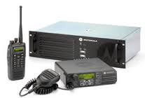

Tech Talk can be heard on select DMR repeaters. Our talk group is on a closed system. Please contact admin@tristatedmr.org to apply to join our group of repeaters that host this cutting edge concept. You’ll need RF access to a local Motorola MotoTBRO repeater that has an active broadband connection to connect to us over the air. Tech Talk is not a general ragchewing channel. It is a portal to ask questions and share details about technical projects. Think of “DMR Tech Talk” as a 24-hr Tech net!
Please bear with us!
This is obviously a new concept so there will be a learning curve for us to manage this website and the networking architecture so more and more people can join us building this repository.
 Latest from DX Zone
- Southgate ARC
- DX Resources
-
- DX Software
- NASA
- NASA to Televise Expansion Operations for Bigelow Expandable Activity Module
- NASA Updates Time for Today’s Media Briefing on Status of Bigelow Expandable Activity Module
- Mark Zuckerberg to Connect with Space Station Astronauts via Facebook Live
- NASA to Brief Media on Status of Bigelow Expandable Activity Module
- NASA Selects Contractor for Safety, Mission Assurance Services
- NASA Awards Financial and Business Management Services Contract